Twisted Pair Cables
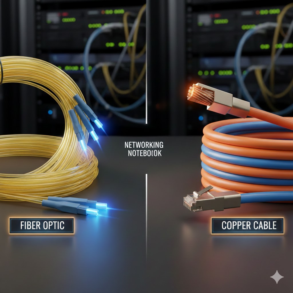
Hello everyone, today we are going to talk about cables, specifically copper cables and fiber cables. Copper and fiber optic cables both have their pros and cons, so let’s talk about it. Copper is an IEEE 802.3 standard that carries electrical signals from the transmitting end to the receiving end and vice versa. They can come in two ways either as a UTP or STP. UTP is Unshielded twisted pair and STP is shielded twisted pair. Shielded and unshielded is pretty self explanatory, shielded contains a metallic or foil shield wrapped around the wires, whereas UTP does not have any kind of metallic or foil shield. The metallic shield can either be wrapped around all the wire pairs or they can be wrapped individually. The wires inside are color coded, the colors are white/orange, orange, white/green, green, white/blue, blue, white/brown, and brown. They both consist of 8 wires, these 8 wires are separated into twos, which are then twisted together. The reason that they are twisted together is to avoid crosstalk and EMI. The connectors that are used to terminate these cables are usually RJ45(Registered Jack) which can be plugged into most network devices such as routers, switches, access points, and more. They have no need for a transceiver as most network devices universally use RJ45 for most of their ports. You will usually see these cables around SOHO environments. Twisted pair cables can go up to speeds of 10Gbps and the most distance that any speed can go up to is 100 meters no matter what. Whether it’s 10 Mbps or 10Gbps, the longest distance is always 100 meters.
Copper Twisted Pair Pros:
- Cost-effective
- Installation for twisted pair is usually easier
- Most network devices support RJ45, so no need for transceivers.
- Can be used with PoE devices
Copper Twisted Pair Cons:
- Shorter Distances
- Susceptible to interference (EMI, Crosstalk)
- Attenuation
- Not as durable
- Lower bandwidth and speeds compared to fiber
- Degradation(copper can corrode over time)
Copper twisted pair is cost effective, easy to terminate and install, and very good performance wise for short distances and SOHO environments but they lack in longer distances, being truly immune to EMI/Crosstalk, and doesn’t perform at the rate fiber optic does. It is still used today and has its uses, you just need to be strategic about it.
Fiber optic cables are much different than copper cables. Their mode of transportation is not electrical signals but pulses of light. Instead of 8 wires, inside the cable there are extremely small thin strands of glass called optical fibers. Fiber cables have two different types called “single-mode” and “multi-mode.” Before I dive into those, let’s talk about the structures of these cables.
Fiber Optic Cables
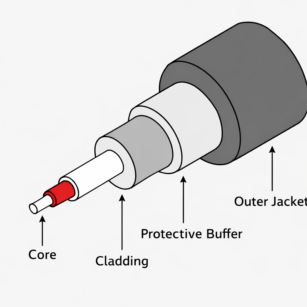
There are four main parts of a fiber optic cable, we will start outward then go inward. The most outer part, the part you can touch is called the outer jacket, after the outer jacket comes the protective buffer, and after the buffer is the cladding and the most important part of the cable is the core. The main workhorse of this cable is the core and the cladding. I have left an image below so that you can visualize it. The core is the part of the cable that is responsible for carrying the light to its destination. But here’s the thing, if it was just the core and no cladding around it there would be no way for the light to be contained inside the cable. If there was no cladding the light would simply leak out and never reach the destination. So what does the cladding do? The cladding is responsible for providing the boundary that keeps the light confined in the wire. This process is called total internal reflection. To help you visualize, I’m going to give you an example, picture a hallway with two parallel walls to the left and right. At the end of the hallway is a bedroom with the door wide open. If I roll the ball completely straight, what happens? It goes straight into the bedroom. But what if I rolled the ball at an angle? The ball would go from one wall and bounce at the other wall, being confined to the hallway. This is what total internal reflection does. It keeps the light that the core is transmitting inside the cable, and because the cladding has a lower refractive index it looks kind of like a zig zag. If the cladding had a higher refractive index the light would not be confined inside the cladding and the light would escape.
Fiber: Singe-Mode
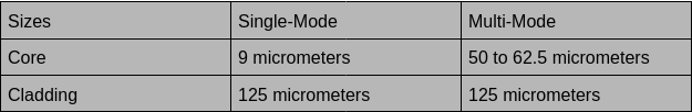
Now what makes single-mode different from multi-mode, let’s talk about it. Single-mode is called that because the core that is responsible for moving the light is really really small. It is so small and narrow to the point that light can only travel in a single line. Think of a flashlight and the width that it’s able to cover, now think of that same flashlight but this time the light is almost the actual shape of a pencil. This is single mode, the actual specifications for single mode is that the core is around 9 micrometers and the cladding is about 125 micrometers. Because the core that’s moving the light is so narrow, the light can travel amazingly far distances with little to no EMI at all! On top of the type of light being transmitted are lasers. The longest range is 10GBASE-ER which can travel up to 30 km. Not only does EMI not impact it, attenuation is minimized, performance is optimized and speeds are super quick. Single-mode cables will usually be found in ISP backbones connecting sites between cities, used to connect data centers, and telecommunication networks.
Fiber: Multi-Mode
Multi-mode basically has the same structure as single-mode, the cladding is still 125 micrometers but the key difference is the size of the core which is about 50 to 62.5 micrometers. As you can see the difference between 9 and 50 is almost 5x as big. So that means it is wider and not as narrow, because the light that the core is supposed the transmit is split into multiple lights which are LED/VSCELs for multi-mode. More usually means better right? Well not in this scenario at all. Yes, multiple lights are traveling through the wire but because of this, some LEDs will arrive at the destination faster than others and some slower. In multi-mode sequential delivery of LEDs are a rarity. When this happens it is called “modal dispersion.” Remember that ball example? Let’s think about it again. Say you have four balls, you have two and your friend has two. You both slide the ball at completely different angles, some closer to you and some a little far down. Well what do you think gonna happen, they will all end up arriving depending on the series of events. Balls thrown at different angles arrive at different times, just like light rays in multi-mode fiber, causing pulse spreading.There is no kind of coordination and the timing of the destination is basically a free for all. This is bad because this limits the amount of distance that multi-mode can travel. There will be a breaking point where the LEDs will have diminishing returns because after a certain point the pulses will spread and overlap. The receiving end will be unable to tell one pulse of LED from another. Multi-mode still reaps the benefits of fiber and is an excellent choice but like I said earlier you need to be strategic when implementing them. It still can travel very far. 1000BASE-SR can travel about 400 meters(4x any copper cable). Multimode are usually most common on same-site buildings, campuses, enterprise LANs or data centers. One more thing I should mention is that since RJ45 was the gold standard for many many years, in order to use fiber on devices you usually need to have some transceivers in order to actually use fiber in today’s age.
Fiber Optic Cables Pros
- Extremely high bandwidth
- Very long transmissions, even multi-mode far surpasses coppers max distance
- Essentially immune to EMI and crosstalk
- Single-mode has much much less attenuation
Fiber Optic Cables Cons
- Very expensive
- More fragile(made out of glass)
- Single-mode can be quite difficult to install
- Doesn’t work with PoE switches (Devices using fiber need separate power.)
- Hard to run a cable tester, especially when connecting sites 30km apart.
Leave a Reply