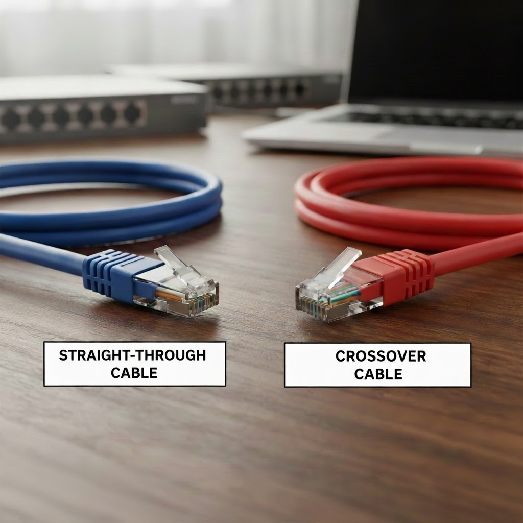
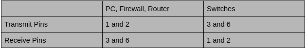
Today I will be discussing straight-through cables and crossover cables. Straight-through cables and cross over cables both have their use cases. They both serve an important purpose and can’t just be used any way you want to, well because of new technology we can but for the sake of learning the purpose we will dive into what they are and how the new technology has fixed it. When a PC, Firewall, or a Router communicate they communicate on something what we call pins. A standard copper cable will usually have 8 pins, and are usually color coded. There is one color code for T568A and another code for T568B. PCs, firewalls, and routers, all these devices transmit on pins 1 and 2 and receive on pins 3 and 6. On the contrary, switches transmit on pins 3 and 6 and receive on pins 1 and 2.
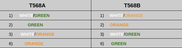
So if a PC is connected to a switch, it will be fine with a straight-through cable as the transmit pins will clearly align with the receive pins perfectly. But what if it was a PC connected to a PC, or a switch was connected to a switch, what would happen? Well as you can guess it would not be any good! The transmit pins would be connected to the transmit pins, and the receive pins would be connected to the receive pins. So basically both PCs will be talking to each other but no one is listening. In other words the PC is talking to a brick wall lol. This is where cross-over cables come to shine in situations like this. The crossover cable crosses(switches) the wire color pairs that are green and orange, so in a T568A cable White Green is at 1 and green is at 2. On T568B White orange is at 1 and Orange is at 2. Because of this setup when a PC is connected to a PC or a switch is connected to another switch, the transmit pins will send traffic to the receive pins. Have a look at the table below to visualize what I just explained.
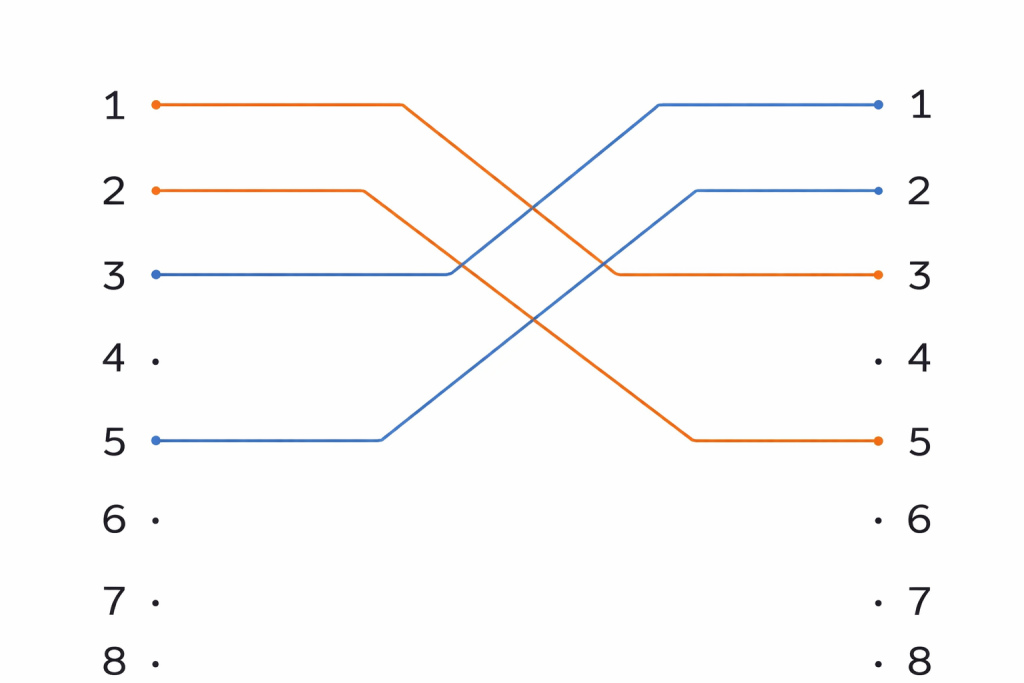
As you can see from the chart above, I have placed only the white and orange pairs so you can visualize what’s happening without any distraction from the other colors. To be technically correct, I want to emphasize that what I am about to say applies to speeds of 10/100 Mbps ONLY. (In this example, only two color wires are chosen when it comes to 1000 Mbps all four color wires will be transmitting and receiving simultaneously.) It operates differently at speeds higher than that but for the sake of learning A and B functions will only be talking speeds 10/100 Mbps. As you can see in the chart white/green is at 1 and green is 2. On the other end white/green is at 3 and 6 is green. White/green and green will transmit and white/green and green on B will receive. Same goes for T568B, white/orange and orange will transmit and white/orange and orange on the other side will receive. Remember PC transmits on 1 and 2 and receives on 3 and 6, this is what makes the crossover cable work.
Auto MDI-X
Now about the new technology that has made being intentional about whether a cable is straight-through or crossover obsolete. This feature is commonly found on most devices nowadays and that feature is called Auto MDI-X. This will be installed on a switch or router, and it automatically detects what the device on both ends of the cable are transmitting on. With this detection, it will adjust the wire pins internally if need be, allowing for the transmit and the receive pins to be always aligned no matter what type of cable is used. If a switch is connected to a switch and I put a straight-through cable, if you’ve read this far you already know what will happen. Communication will fail due to TX and RX mismatch, but what if I turn on MDI-X? Well it will detect that both switches are transmitting on 3 and 6 and receiving on 1 and 2, through that detection it will swap the TX and RX pairs internally.
Leave a Reply