Today we’re going to dive into an Ethernet Frame header and trailer, and what it entails. Frames are a Layer 2 PDU(Protocol Data Unit) that gets forwarded between hosts that are usually in the same broadcast domain or VLAN. Ethernet frames are also vital for transporting packets across networks because a new ethernet frame header and trailer needs to be applied at every hop it takes. Let’s dissect the header and trailer so you know what truly is happening when data is encapsulated at layer 2.
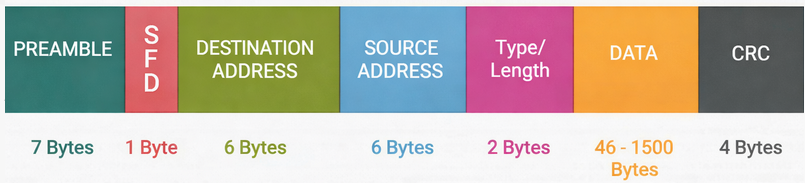
Preamble
The ethernet frame starts out with preamble and SFD, although there is a caveat to this. (Preamble and SFD are not officially a part of the frames, and during packet captures you will not see them at all as they are created and destroyed at every switch’s NIC). Preamble and SFD are both layer 1 as they are just signals. The preamble has a binary of alternating 1s and 0s for 7 bytes. It will look something like this 10101010101010. This is to tell the receiving switch that they should be expecting an ethernet frame very soon, and the purpose of letting the receiving switch know this is so that the receiving switch can synchronize its clock with the sender’s bit timing. Now what does this mean, I hope I can break this down in a way that you can understand. On a link, the sending switch is sending the ethernet at a certain speed. Computers talk in 1s and 0s, 1 being on or high voltage or 0 being off or low voltage. So when data is being sent at a certain speed, the receiving device must be able to read those 1s and 0s at the same speed as the data is moving. If the receiving switch is reading the 1s and 0s at a slower pace than it is moving, 0s can be interpreted as 1s, and 1s can be interpreted as 0s. Let me try my best to make this digestible, say you want to track the color of shirts marathoners are wearing, you think you have plenty of time to watch them and write at the same time so you choose to write Blue instead of something shorter like Bl. When the 1st pack of runners come, they are running at 5:45 minute pace, and now you’re scrambling to get them all and now you’ve accidentally marked the wrong colors for some of them. But what if someone warned you that the 1st pack comes in at a certain pace, you would have been more prepared and accurate than just randomly guessing. The preamble prepares the switch to interpret the binary at the correct pace.
SFD
After the preamble comes the SFD which stands for Start Frame Delimiter. This is only 1 byte and consists of the same alternating 1s and 0s and right before the byte ends the last two bits are 11. It looks like this: 10101011. This is very important and this 11 at the end of SFD tells the receiving switch that the preamble is done, and this is the mark of the start of the ethernet frame. With an SFD the switch will start interpreting the destination MAC address at the time it is supposed to start. Without an SFD, the receiving switch would have no idea when a frame would start or end.
Destination and Source MAC
After the SFD, comes the destination MAC address. This field is 6 bytes and when the switch reads this field it knows exactly where to forward the frame. Once it looks at this field it knows who the intended recipient of the frame is and forwards it accordingly. The source MAC is also recorded right after the destination MAC. This information is not as vital to the switch compared to source MAC when it comes to forwarding, but this field in the header is the field that actually populates the CAM or MAC address table. When the switch receives the frame, if the source MAC is not recorded then when it reads the MAC address it will record that MAC address along with the port where it came from into the CAM table. This is vital because whenever traffic destined for that address comes, it knows where that address exactly is. The source MAC is also an important field for the receiving host, the host now knows the return address for that specific frame so it will not need to perform an ARP request to send replies back to that address.
Type/Length
Next in the header is the Type/Length field. This field is 2 bytes long and varies on platforms such as Ethernet II or 802.3. Ethernet II is more modern and uses the Type field, and 802.3 tends to be Length. The type field will show the receiving switch what Layer 3 protocol is being used. It can be IPv4, IPv6 or ARP, and there are special codes used for each one.
IPv4 = 0x0800
Ipv6 = 0x86DD
ARP = 0x0806
The length field just tells the receiving switch the length of the payload(NOT the header or trailer). It is usually one or the other and whether type or length is chosen depends on a decimal value. If the value is less than 1500, then the 2 bytes after source MAC will be the length field. If the decimal value is over 1536, then the 2 bytes after the source MAC will be the protocol field.
≤ 1500 = Length (maximum payload size in bytes)
≥ 1536 = Type (EtherType)
FCS
After the type/length is the actual data being sent, that is being encapsulated. And last but certainly not least is the FCS which stands for frame checking sequence. This field is used for error detection and making sure that the ethernet frame that has been sent across the broadcast domain has not been tampered or corrupted in any way. An ethernet frame has to travel through layer 1, and layer 1 can have a host of issues such as duplex mismatches, bad connectors, bad terminated cables, failing NICs, bad cables, EMI and so much other stuff. These layer 1 issues can corrupt the data meaning that the data sent is not the same data received. How does the switch know if the frame has been corrupted? FCS. FCS is a checksum value that is added to the trailer of the ethernet frame. This value is calculated with something called CRC (Cyclic Redundancy Check). CRC does polynomial division and calculates a value based on the whole ethernet frame from the source MAC all the way to the end of the data payload. This value is unique to the frame, so when it’s traversed across the network the value should be exactly the same. When a packet traverses a network and the receiving host is decapsulating the frame, before it accepts it as valid it does the CRC calculation based on polynomial division again. If the number matches the one in the sent frame, the packet is accepted as valid and processed. But if the number does not match the value in the FCS in the original frame even if it’s off by one bit, the whole ethernet frame is considered as corrupt and invalid leading the whole ethernet frame to be discarded.
The minimum size of an ethernet frame is 64 bytes total and 46 bytes for the payload. If the payload does not meet the minimum threshold then something called “padding” is added. Padding is extra bytes added when the minimum size is not met in order to make it meet the minimum. It is usually just 0s which are added after the payload before the FCS. The maximum size of an ethernet frame is 1518 bytes without a VLAN tag and 1522 bytes with a VLAN tag.
Leave a Reply