Today we’re going to dive into input errors and output errors. Input and output errors can be found under the “show interface” command on cisco CLI. These are usually just a counter that increments every time a specific error happens that stops a frame from being successfully transmitted. Whenever the input or output error increases, this is usually the case that a layer 1 issue is occurring preventing a successful transmission.
Input Errors
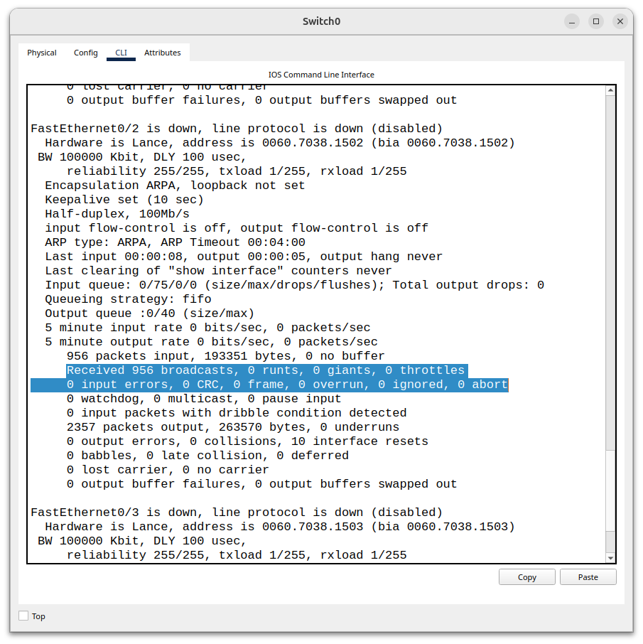
Input errors are errors that are received on an interface only. The main types of input errors are runts, giants, frame errors, and CRC errors. Whenever one of those issues occur on a receiving interface, the input error increments by one.
Runts are frames that have failed to meet the minimum size of bytes. The minimum size required for an ethernet frame is 46 bytes for the data payload and 64 bytes total including the header and trailer. If a frame happens to be received on an interface and it is under 64 bytes, the frame is automatically discarded and the input error counter goes up one. 64 bytes was chosen as a minimum when half duplex networking was more common in order for the PC’s NIC to actually detect that a collision has occurred.
Giants- Another error that can occur is a frame being delivered over the MTU (Maximum Transmission Unit). If the frame is larger than 1518 bytes or 1522 bytes with a VLAN tag, then it is considered a “giant” and is too large to process. If a frame arrives on an interface of 1530 bytes, that frame will be discarded and the input error counter will increase by one. The next error is a frame error.
Frame Error- A frame error occurs when a frame arrives on an interface that has an illegal or malformed format. A common type frame error is a misalignment. If the receiver’s clock recovery fails to stay synchronized with the sender’s bit timing, it may cause the receiver to interpret the 1s and 0s wrong and lose proper byte boundaries, confusing 0s for 1s and 1s for 0s leading to inaccuracy. Another wrong thing that can happen in a frame error is that the bytes are not true bytes meaning that there could be leftover bits. Say the frame received is 1010111110 total, that is 1 byte with 2 remaining bits which are 10 left over. That is a completely invalid format. Byte boundaries are messed up when there are leftover bits because the receiving device is not accurately interpreting the start and end of bytes. Misalignments can happen because of collisions, EMI, duplex mismatches, or bad cabling.
CRC Errors- The last input error we are going to talk about is CRC errors. These errors occur when data has been corrupted during transmission. Every ethernet frame that traverses the network is checked for errors or corruption when it arrives at the destination host. There is a dedicated field that’s sole purpose is to make sure that no corruption has occurred during transmission called the frame checking sequence. Before an ethernet frame is sent across the network, the headers and the payload are run through a polynomial division algorithm called the cyclic redundancy check. When it gets run though this algorithm, a checksum is calculated and applied to the trailer of the ethernet frame. When the receiving host decapsulates that same ethernet frame, it runs that same mathematical algorithm and if the checksum matches the original, then the frame has not been corrupted but if it doesn’t match then the frame has been corrupted somewhere along the transmission. When that happens the entire ethernet frame is discarded and the CRC error counter goes up by, incrementing the input error counter as well.
Output Errors
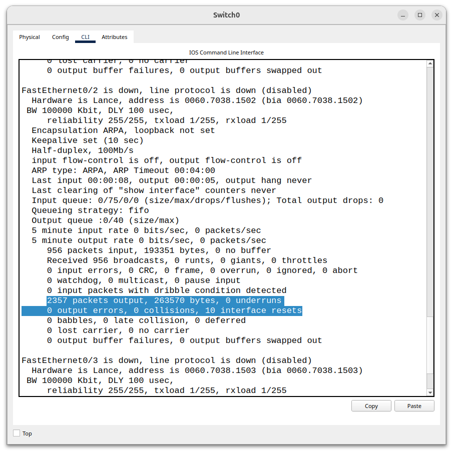
Collisions- Now that you know what input errors are, we’ll talk about output errors which are errors that occur when the host is trying to transmit a frame. These errors prevent the frame from transmitting onto the wire or failing to arrive at the destination at all. The first error that can cause a frame to not arrive at the destination host. The first output error is a collision. Collisions are more common in half duplex environments, where two hosts transmitting at the same time can cause signal interference essentially corrupting the data trying to be sent. When a collision happens, the collision counter and output error counter increment by one.
Late Collisions- Another output error is late collisions, these are collisions that occur after the 64th byte. The first 64 bytes are the standard size for detecting collisions via CSMA/CD. Collisions must occur before 64 bytes for CSMA/CD to detect it. When a collision occurs on a half duplex network, the collision signal needs to reach back to the sender so it can stop transmitting. 64 bytes was chosen because if it were to be any less than that, a collision would happen before the sender finished transmitting, and the sending host would not detect it in time, causing the receiving host to receive a corrupted frame. Any collision that happens after the minimum size 64 bytes is a late collision which usually means that there is a duplex mismatch, or bad cables. The standard for CSMA/CD is 64 bytes so a late collision is a major sign of an anomaly.
Underruns- The last output error we are going to talk about today are underruns. Underruns occur when a link connected to an interface is configured to operate at a certain speed (10, 100mbps) and is expecting to receive data at that speed to transmit. An underrun occurs when the switches NIC can’t provide the data at the rate that the link wants to transmit the data as it’s being bottlenecked from the NIC. This causes a “data starvation” problem, when this occurs the underrun and output error counter increments by one. Underruns can happen when there’s a sudden burst of large frames or high-speed transmissions.
Leave a Reply