Today we are going to dive into the IPv4 header that is added when data is being encapsulated. The IPv4 header is vital for network communication, and gives instructions on how to deal with data. Although the IPv4 header can look daunting at first, after you are familiar with the concepts it makes sense as to why each field is there like a puzzle.
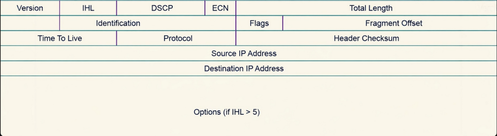
Version
The first field in the IPv4 header is a 4 bit field called “Version.” This field lets the receiving host know which version of IP is being used. An IP can be IPv4 or IPv6, and their header fields are different with different functions. A receiving host needs to know which version of IP is being used to accurately interpret the rest of the header. IPv6 header doesn’t have an identification or flags field so if the receiving host receives an IP packet that version says its IPv6 header but it’s actually an IPv4 that can cause error when trying to read the header causing the header to be misinterpreted and eventually the packet would be dropped.
IHL
The next field is IHL which stands for Internet Header Length and is 4 bits as well. This field is important because it allows the receiving host to determine the size of the IPv4 header. The IPv4 header contains another field called “options” which we’ll talk about later, and options can vary from 0 to 40 bytes depending what services are being used. This can lead to fluctuating header sizes, and if the receiving host does not know the size of the header, it will not be able to accurately determine the boundary separating the header from the payload. IHL is 4 bits but it represents the header length in 32 bit words.
32 bits / 8 bits = 4 bytes
To find the IHL length, you calculate the IHL value and multiply it by 4. So if the IHL is 6 then the total size is 24 bytes. If the IHL value is 5, then the header size is 20 bytes. The minimum size for IHL is 5 which equals 20 bytes. The whole header and all its fields combined is 20 bytes without any options added.
DSCP
The next field is called DSCP which stands for Differentiated Services Code Point and is 6 bits long. This field is used to provide QOS services at the layer 3 level. It allows the sending host to prioritize and classify packets based on level of importance. Delay-sensitive traffic such as video or voice have higher DSCP values, and lower traffic are characterized by lower DSCP values. The DSCP value can range from 0 to 63, and what number is chosen for that packet indicates the kind of treatment or per hop behavior that packet will receive. Per hop behavior is how a packet will be treated at each router, each router has different treatments for DSCP markings usually configured by a network admin. The queue the packet is placed into, the max allowed bandwidth, and how likely a packet is to be dropped all differ between routers. So even though a packet has the same DSCP value, its treatment is determined per hop or router. DSCP does not guarantee priority, and routers determine how they will treat the marked packet.
ECN
The next field is still a QOS field called ECN which means Explicit Congestion Notification. This field is 2 bits long directly after DSCP and is vital for preventing dropped packets and retransmissions. It’s a part of the differentiated services field. During a normal occurrence without ECN, the only way for the sending host to know if it needs to slow down its transmission rate is detecting packet loss. When routers along the path forwarding a packet begins to experience congestion, routers would normally drop packets. When the sending device detects packet loss, it slows down its transmission rate in order for the receiving host to process more data. ECN allows congestion notifications without packet loss, but only if every router along the path supports ECN. When a packet is traversing through routers to get to its destination, if the packet arrives at a router and it detects that the routing path is becoming congested, instead of dropping the packet to force the transmission rate to slow down it marks the packet by setting the CE codepoint in the ECN portion of the header which means Congestion Experienced. When the receiver receives the packet that has been marked with the CE, it then sends a ECN-echo back to the sender which notifies the sender that congestion was experienced. Once the sender receives the packet with a ECN-echo, it will then slow down the transmission. (Since this is an IPv4 blog, I don’t want to get carried away but the ECN-echo flag is set in the TCP header, the CE notification is in the IPv4 header).
Total Length
The field after ECN is total length which is 16 bits in length. This field represents the total size of the entire header and payload. This will help the receiver determine the end of a packet. Total length is vital for two separate packets that don’t belong together to not get mixed up, by knowing the exact bytes of each packet.
Identification
The first field in the second row is Identification which is 16 bits. When a packet exceeds the MTU but wants to still be transmitted, the packet will be fragmented into multiple packets and they will all be routed separately. Since this is the case the receiving host will be getting multiple packets that belong to one larger packet. How will the receiving host know which fragment belongs to what packet? Identification solves this by uniquely adding the same identifier to each fragment. So say a packet needs 4 fragments, and they all belong together. If the identification value is 4, each fragment will have the value 4 to represent them and make it easier for the receiver to tell they belong together. This is crucial to accurate assembly after fragmentation has taken place. Without the identification field, the receiving host would have no idea which original packet the fragment belongs to.
Flags
Identification works hand in hand with a field called flags and fragment offset. Flags is a 3 bit field that controls whether the packet may be fragmented or whether more fragments are coming. The 3 bits represent 3 flags, the first bit represents the reserved bit which is always set to 0, the second bit is DF which means Don’t Fragment, and the third bit is MF which means More Fragments. If there is a packet that has the DF flag set to 1 that means that it is instructing routers to not fragment this packet under any condition. If a packet reaches a router where the packet is larger than the link’s MTU, then the packet is dropped and an ICMP message is sent back to the sender indicating that a fragmentation is needed. If a MF flag is set to 1, it means that the packet has been fragmented and that more fragments are to come. If a MF flag is set to 0, that fragment is the last fragment of that original packet.
Fragment Offset
Fragment Offset is also a work with flags and Identification. It is a 13 bit field that is key for the receiving host knowing how to arrange the fragments. Fragments arrive at the destination host whenever they arrive, meaning that sometimes they can arrive at the destination out of order. In order for the receiving host to know the exact sequence of the fragments to put them in order, fragment offset plays a huge role in assisting with that. Fragment offset marks each fragment with a value that is then used to determine the exact place of the fragment when compared to the original unfragmented IP packet. With fragment offset, the receiving host is able to find out the exact position of where the fragment belongs, essentially reassembling the packet back to its original state. Fragment offset is measured in 8 byte units, so if a fragment offset has a value of 100, than you would do 100 * 8 which would equal 800. If it were 1000, the fragment offset would be 8000. Without fragment offset, the receiving host would have no idea how to reorder the packet back to its original state before fragmentation.
TTL
The third row of the IPv4 starts with TTL which stands for Time to Live measured at 8 bits. This field is essential to prevent routing loops, where a packet is endlessly traversing routers with no destination being reached. The TTL is hop based and when a value is set on the TTL, the packet is only allowed to traverse that many hops. For example if I set the TTL of a packet with an initial value of 64, the packet will traverse up to 64 hops until it becomes discarded. Every router equals one hop, so each time a packet with a TTL set arrives at a router, the router decrements the TTL value by one. This happens continuously and if the packet does not arrive at its destination by the time the TTL equals 0. Then the packet will be discarded and an ICMP message will be sent back to the sender stating “Time Exceeded.” This prevents a packet from traversing the network endlessly wasting router bandwidth and processing overhead.
Protocol
The field after TTL is the Protocol field which is also 8 bits. This allows the receiving host to know which layer 4 protocol is encapsulated within the IP packet. This allows the receiving host’s network layer to forward the data to the right layer 4 protocol so that the process is a smooth transition. Protocols have unique values, TCP is 6, UDP is 17, and ICMP is 1. This allows the right protocol to receive the right data to accurately perform multiplexing.
Header Checksum
Header Checksum is the last field of the third row and is 16 bits long. This is a field that ensures the integrity of the whole IPv4 header(header only not the payload). It makes sure that the IPv4 header has not been altered, corrupted or manipulated during transit. A changed header can lead to detrimental outcomes like a manipulated destination IP causing someone else to receive the IPv4 packet. Before the IPv4 packet is created a mathematical operation such as one complement’s sum is performed on the whole IPv4 header and a value is determined and placed in the header checksum field. As the packet traverses the network, every router must do the one complement’s mathematical operation again because of varying values that change at each router such as TTL. This value is then placed in the header checksum, and when the packet arrives at the receiving host the same one’s complement’s mathematical operation is performed again over the whole header. If the value produced matches the last router’s header checksum then the header is determined valid, if it is different then the header is considered corrupt and the whole packet is discarded ( This is very similar to the FCS in an ethernet frame).
Source and Destination IP
The source and destination IP addresses are then placed in their own rows after the third row and are both 32 bits each. The source IP serves as a return address for the receiving host and the destination IP provides the intended recipient. Routers use the routing table along with the destination IP to determine where to forward a packet.
Options
The last optional field in the IPv4 header is Options and it can range anywhere from 0 to 320 bits depending on the services used. The options field provides many routing features that are now obsolete. The most well known services that this field offers is record routing, source routing, and timestamps. Because of the different types of services provided, the options field will always have varying sizes depending which options are chosen. Record routing is a feature that allows the packet to be tracked at every router it reaches. It allows the sender of the packet to request that each router along the path record its IP address in the packet as it is being forwarded. By the time the packet gets to the receiver, it has a list of every router that the packet traversed. It is obsolete because tools like traceroute now exist. Another feature of options is source routing. This allows the sender to dictate the specific path that a packet should go. The sender dictates the exact sequence the packet will take, and the exact intermediate routers it must be in contact with on the way to the destination. The sender sets the detailed instructions and the intermediate routers follow them. Routes with source routing enabled can specify every router or hop, or only a select few of routers or hops. Another major feature of options is timestamps. When timestamps are enabled by the sender, every router that the packet travels through must record the exact time it received the packet. The time will be recorded at every intermediate router, allowing the receiver to see how long it takes the packet to arrive at each intermediate router. This can be used for troubleshooting and performance monitoring.
🔗 IPv4 (Wikipedia) – Header overview and fields – A detailed encyclopedia entry explaining IPv4, its structure, and header fields.
🔗 IPv4 Header Fields Explained (CCNA Notes) – A concise guide walking through each IPv4 header field and what it means.
🔗 IPv4 Header Detailed Breakdown (Study CCNA) – Another clear explanation of all standard fields in the IPv4 packet header.
🔗 Cisco‑style IPv4 Packet Explanation (Cisco training page) – Notes on how IPv4 header fields are used in routing and fragmentation
Leave a Reply