During the past few articles I have talked about VLANs, VLAN tagging and all the good layer 2 things. But I didn’t discuss how hosts on different VLANs communicate, so let’s dive into it. The process of a host in one VLAN communicating with a host on another VLAN is interVLAN routing. This is the process of giving a certain VLAN a default gateway and that default gateway then routes it to the destination host. Reminds you of anything? This process is basically the same for a host in a LAN to communicate with a host in a different LAN. Well they don’t call it VLAN for no reason.
InterVLAN routing can be done by layer 3 devices such as a router or layer 3 switch. When interVLAN routing is configured on a router it is called “Router on a Stick.” The reason it’s called router on a stick is because one link connected to the router is routing between VLANs. So the “stick” is that one link. The way ROAS works is by having subinterfaces. A subinterface is multiple logical interfaces operating in one physical interface. For example, say a router has an interface labeled f0/0. A subinterface can be made by adding a period and a number after the f0/0. Configuring the subinterfaces would look like this:
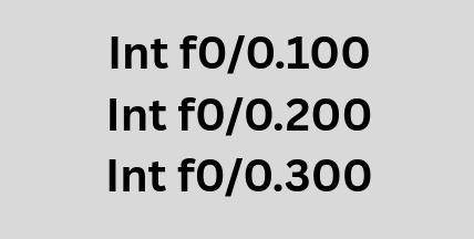
As you can see I wrote 3 different subinterfaces. It is common practice to use the VLAN number but not mandatory, so it’s easier to distinguish quickly. So 0.100 would be VLAN 100, 0.200 would be VLAN 200, and 0.300 would be VLAN 300. These subinterfaces will act as an actual interface. On a regular LAN with a default router, the physical interface is the default gateway and when a host on that gateway needs to reach the external network it forwards data towards the interface and it gets routed to the external network. In ROAS, the hosts send untagged data to the access switch, the switch then adds a VLAN tag as it egresses or exits out of the trunk port and forwards it towards the router. When the router receives that data it inspects the VLAN ID of the incoming frame and routes the packet using the subinterface connected to that VLAN, the data gets decapsulated like a regular packet, looks at the destination IP, does a routing table lookup, then re-encapsulates it with the correct VLAN tag and forwards it to the appropriate outgoing interface. Each subinterface represents a VLAN, and whenever traffic for that VLAN arrives at that router that subinterface acts as the default router for that VLAN. So if PC1 in VLAN 200 sent data to PC2 in VLAN 300, the packet would be encapsulated with a VLAN 200 identifier, sent to the default gateway in this case interface f0/0.200 and then goes through the decapsulation as a normal packet would, looks at the destination IP and if that IP is in the same subnet as one of the subinterface for example say VLAN 300 then the router adds the VLAN 300 tag and sends the data on its way. So the subinterface is basically the default gateway forwarding traffic on behalf of all the hosts on that VLAN.
A layer 3 switch can also perform InterVLAN routing, and even way faster than routers. The reason this is the case is because unlike traditional routers that rely on CPU software processing for packet forwarding, a layer 3 switch is hardware based with ASICs (Application Specific Integrated Circuit) installed in the motherboard. These are specialized chips designed to help the layer 3 switch perform high speed switching and routing at wire-speed. Wire-speed means a network device can forward data at the maximum speed of the physical connection without being limited by software processing. (Important to note that the CPU still handles control-plane tasks such as routing protocols). The difference between ROAS and layer 3 interVLAN routing is that a layer 3 switch does not use a physical interface at all. It uses a logical interface called the SVI (Switched Virtual Interface). This interface is not connected to any port, and is completely logical. In order for the different VLANs to communicate, each VLAN will need to be assigned to an SVI. The SVI will need to be up/up (administratively/operationally up) and be assigned a network address of the VLAN. The SVI serves as the default gateway for its VLAN and routes the data to the correct VLAN. When a switch receives a packet with a destination IP for a different VLAN, it does a routing table look up, see that the destination IP matches the same subnet as SVI, then it will forward the data with the appropriate VLAN tag to the outgoing interface.
The process works the same as ROAS, but I will list it out in steps below.
- PC1 in VLAN 10 wants to send data to PC2 in VLAN 20. They are both connected to a layer 3 switch.
- PC1 in VLAN 10 sends the data to the layer 3 switch. (The port is an access port so the ethernet frame is sent untagged, as the switch port is configured to only carry traffic for VLAN 10)
- If the PC was not directly connected, then the switch would have added a VLAN tag if it is going to traverse via trunk link. It’s important to note that switches usually put VLAN tags as they are exiting or “egressing” out of a port onto a trunk link.
- The switch receives the data, decapsulates it until the network layer, and does a routing table lookup.
- The switch sees that the destination IP belongs to a subnet on one of the SVIs.
- The switch encapsulates the packet with a new ethernet frame (Source MAC of SVI, Destination MAC of PC2) and forwards it to the destination.
- If PC2 was directly connected to a switch, the switch would send it without a tag. If there was a trunk link instead, a VLAN tag identifying VLAN 20 would be added by the switch.
When determining a topology for interVLAN routing, one other thing to consider is that ROAS has a single point of failure. If that one link goes down, no host in any VLAN will be able to communicate with other hosts in another VLAN.
Leave a Reply