Hi, today I am going to talk about STP (Spanning Tree Protocol). STP is a layer 2 redundancy mechanism widely used to control layer 2 loops and broadcast storms logically. STP is an amazing protocol because not only does it prevent broadcast storms, but it provides redundancy so if something in the topology fails an alternate path is calculated. What is redundancy? Redundancy is the act of multiplying the same devices, or cables in order to prevent single points of failures. So instead of having one router, redundancy is having 2 routers one for the main operation and one for a backup in case the primary router fails. Same thing with cables, instead of having one cable connecting two switches, what about having 4 cables connecting the switches so if one fails there are 3 more for backup essentially eliminating a single point of failure and providing higher availability than if you were just to have only one cable or router.
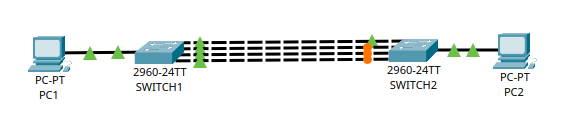
From the example above, having multiple links connecting two routers sounds like a great idea in terms of redundancy but in practice it is not that great. What would happen if I took two switches and plugged in redundant links between them. A broadcast storm would happen, where an excessive amount of broadcast traffic overwhelms a network device such as a switch. When a broadcast storm happens, a broadcast is sent and loops endlessly with no end in sight consuming a lot of the switch’s CPU. I put a photo below and as you can see Switch1 is on the left and Switch 2 is on the right.
Here’s how a broadcast storm would happen step by step.
- Say PC1 wants to send data to PC2, but performs an ARP request first.
- Since an ARP request is a broadcast frame, the ARP request would get flooded out of all the four ports of switch1.
- Switch2 will receive all four of those ethernet frames on all of its open ports.
- Switch2 will look at the source MAC of the first frame that arrived and add it to the CAM table. Switch2 ignores the other 3 copies when it comes to MAC address learning.
- Since the ethernet frame is a broadcast, it will get broadcast to all the ports except the port where the MAC address was recorded. So if it recorded Port 1, it gets flooded out again at port 2,3, and 4.
- That means PC1 will receive those same 3 ARP requests again. That means it will record the source MAC of one port on the CAM table, and send it out of the other 3 ports AGAIN.
- Switch 2 will receive those 3 ARP requests, record the source MAC of one port and forward it out of the remaining 3 AGAIN.
As you can see this will eventually be an endless loop, and the hope of having redundancy doesn’t even matter when the switch is overwhelmed and not working the way it’s designed to work. The switch’s CPU will be occupied processing the same ethernet frame over and over again. Legitimate traffic can get lost in a broadcast storm, and in drastic cases the network can become unusable. The example that I put here is for ARP frames, but this can happen with any broadcast frames such as DHCP discover and request.
So how do you stop a broadcast storm while reaping the benefits of redundancy? STP is the answer. Spanning Tree Protocol is a layer 2 protocol that is designed not only to provide redundancy and backup paths but it is also designed specifically to prevent layer 2 loops. The best part about it is that it does this logically, no physical cable or devices need to be added. STP provides a loop free logical topology where ports have different roles and states such as blocking, listening, learning, and forwarding. Switches are also assigned a specific role (root bridge) and they all work together to make sure no redundant links are active, and if there are redundant links in the physical topology they are put in a blocking state logically. STP achieves a loop free topology by electing a Root Bridge, the calculating the shortest path to the root bridge for all the other switches, and finally blocking redundant path.This is a dynamic protocol, meaning that if anything in the topology changes like if a link fails, the STP will do a recalculation and provide an alternate active path. STP makes sure that there is only one active path to a destination. STP is an open standard defined by IEEE 802.1D but Cisco has their own STP called PVST+ (Per VLAN Spanning Tree). It functions the same way, but there is a separate topology instance for each VLAN, allowing for different root bridges and load balancing across VLANs.
Leave a Reply